Our First CPU, Part 1: Fetch and Decode
A RISC-V processor that does one thing at a time. The program counter, the register file, and turning a 32-bit word into "what to do".
In this article
What are we trying to do?
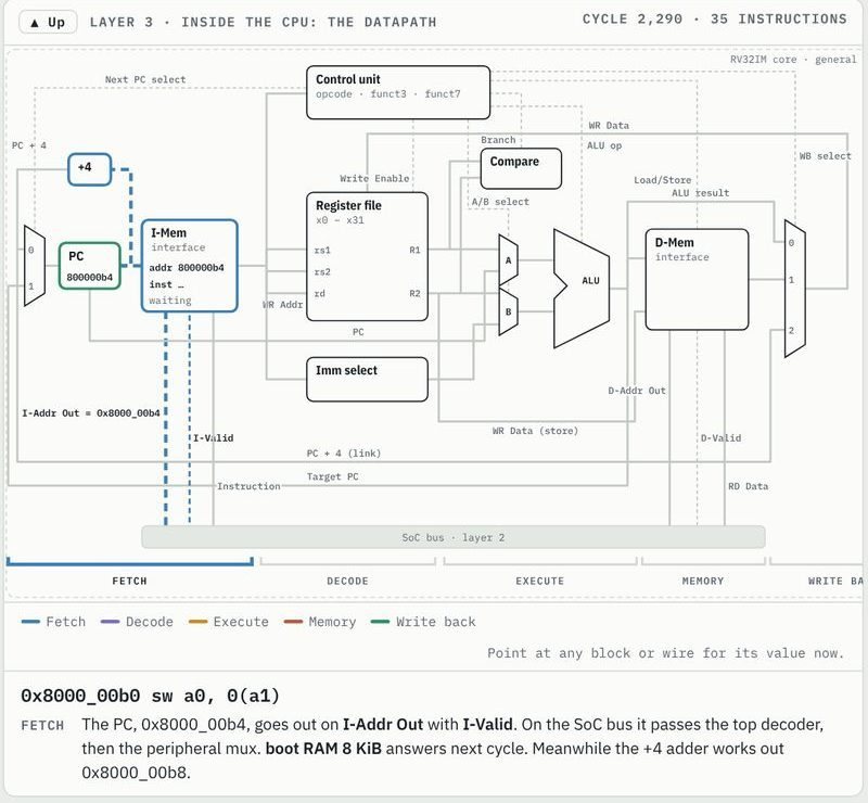
We have a bus and devices on it. Now we need the thing that drives the bus: a processor that reads instructions from memory and carries them out. We will implement RV32I, the base integer instruction set of RISC-V, because it is small (about 40 instructions), regular, and every compiler supports it. GCC will compile our C into it, and our hardware will run what GCC produces.
Many CPUs are pipelined: they work on several instructions at once. Ours is deliberately multi-cycle: one instruction at a time, in a few steps. It is slower, but every signal means one thing at a time, which makes it far easier to build, test and understand. It still runs games at 60 frames a second.
One instruction, step by step
Every instruction goes through the same states:
- Fetch: put the program counter (PC) on the bus, wait for the instruction word.
- Decode: work out what the word means and read the source registers.
- Execute: compute: an addition, a comparison, an address, a jump target.
- Memory and Write back: only for loads and stores, one bus access more.
The state machine that drives this is in part 5. In this article we build the pieces the first two steps need: the PC, the instruction register, the register file and the decoder.
The fetch stage
Fetch needs to remember two things: where the next instruction is (the PC), and the instruction it just read (the IR). The whole module is a dozen lines:
13module nt_fetch #(14 parameter [31:0] RESET_PC = 32'h0000_000015) (16 input clk,17 input resetn,18 19 input pc_we,20 input [31:0] next_pc,21 input debug_pc_we,22 input [31:0] debug_pc,23 output [31:0] fetch_addr,24 25 input ir_we,26 input [31:0] ir_in,27 28 output reg [31:0] pc,29 output reg [31:0] ir30);Two write enables come from the control unit: pc_we when an instruction completes and the PC moves on, and ir_we when the fetched word arrives from the bus.
31assign fetch_addr = pc_we ? next_pc : pc;32 33always @(posedge clk) begin34 if (!resetn)35 pc <= RESET_PC;36 else if (debug_pc_we)37 pc <= debug_pc;38 else if (pc_we)39 pc <= next_pc;40 41 if (ir_we)42 ir <= ir_in;43endLine 31 is the one subtle bit. When an instruction commits, the next fetch must already go to the new PC, but the PC register only takes the new value at the clock edge. So fetch_addr is next_pc in the commit cycle and the register otherwise. That saves a whole cycle per instruction.
On reset the PC becomes RESET_PC, which the SoC sets to 0x8000_0000: the boot RAM.
The register file
RV32I has 32 registers, x0 to x31, each 32 bits. x0 is special: it always reads 0, and writes to it are thrown away. That makes many instructions free: mv a0, a1 is really addi a0, a1, 0, and nop is addi x0, x0, 0.
13module nt_regfile (14 input clk,15 16 input [ 4:0] raddr1,17 output [31:0] rdata1,18 input [ 4:0] raddr2,19 output [31:0] rdata2,20 21 input we,22 input [ 4:0] waddr,23 input [31:0] wdata,24 25 input debug_we,26 input [ 4:0] debug_waddr,27 input [31:0] debug_wdata28);Two read ports (most instructions read two registers) and one write port. The debug port is for a hardware debugger on other boards; on the Tang Nano 9K it is tied off.
29reg [31:0] regs [1:31];30 31always @(posedge clk)32 if (debug_we && debug_waddr != 5'd0)33 regs[debug_waddr] <= debug_wdata;34 else if (we && waddr != 5'd0)35 regs[waddr] <= wdata;36 37assign rdata1 = raddr1 == 5'd0 ? 32'd0 : regs[raddr1];38assign rdata2 = raddr2 == 5'd0 ? 32'd0 : regs[raddr2];Look at line 29: the array only has entries 1 to 31. There is no register 0 to store; reads of address 0 return a constant zero, and writes to it are skipped. Synthesis maps this array to the FPGA's distributed RAM.
x0.Decoding an instruction
The decoder looks at the instruction word and produces everything the later steps need to know. RISC-V makes this easy because the fields are always in the same place:
64wire [6:0] opcode = ir[6:0];65wire [4:0] rd = ir[11:7];66wire [2:0] funct3 = ir[14:12];67wire [6:0] funct7 = ir[31:25];68 69assign rs1_addr = ir[19:15];70assign rs2_addr = ir[24:20];opcode (bits 6:0) says which kind of instruction it is. rd is the destination register, rs1 and rs2 the sources, funct3 and funct7 refine the operation. The source register numbers go straight to the register file, so the register values are ready by the end of this step.
Immediates
Instructions carry constants, called immediates, but each format stores its bits in a different place. RISC-V chose those places so that the sign bit is always bit 31 and most bits stay in the same position across formats, which keeps this part of the hardware small:
72wire [31:0] imm_i = {{21{ir[31]}}, ir[30:20]};73wire [31:0] imm_s = {{21{ir[31]}}, ir[30:25], ir[11:7]};74wire [31:0] imm_b = {{20{ir[31]}}, ir[7], ir[30:25], ir[11:8], 1'b0};75wire [31:0] imm_u = {ir[31:12], 12'b0};76wire [31:0] imm_j = {{12{ir[31]}}, ir[19:12], ir[20], ir[30:21], 1'b0};| Format | Used by | Range |
|---|---|---|
| I | addi, loads, jalr | −2048 … 2047 |
| S | stores | −2048 … 2047 |
| B | branches | ±4 KiB, even |
| U | lui, auipc | upper 20 bits |
| J | jal | ±1 MiB, even |
{21{ir[31]}} repeats the sign bit 21 times: that is sign extension, so addi a0, a0, -1 really adds −1. The B and J formats end in 1'b0 because jump targets are always even.
Which instruction is it?
Each opcode gets a one-bit flag:
78wire is_lui = opcode == OPC_LUI;79wire is_auipc = opcode == OPC_AUIPC;80wire is_jal = opcode == OPC_JAL;81wire is_jalr = opcode == OPC_JALR;82wire is_branch = opcode == OPC_BRANCH;83wire is_load = opcode == OPC_LOAD;84wire is_store = opcode == OPC_STORE;85wire is_op_imm = opcode == OPC_OP_IMM;86wire is_op = opcode == OPC_OP;87wire is_fence = opcode == OPC_FENCE;88wire is_system = opcode == OPC_SYSTEM;Not every bit pattern is a valid instruction. The decoder checks the extra fields and flags anything it does not know as illegal:
106reg legal;107always @* begin108 case (1'b1)109 is_lui, is_auipc, is_jal: legal = 1'b1;110 is_jalr: legal = funct3 == 3'b000;111 is_branch: legal = funct3[2:1] != 2'b01;112 is_load: legal = funct3 != 3'b011 && funct3[2:1] != 2'b11;113 is_store: legal = funct3[2] == 1'b0 && funct3[1:0] != 2'b11;114 is_op_imm: legal = op_imm_ok;115 is_op: legal = op_ok;116 is_fence: legal = funct3[2:1] == 2'b00;117 is_system: legal = is_ecall_ebreak || is_csr_read;118 default: legal = 1'b0;119 endcase120 if (ir[1:0] != 2'b11)121 legal = 1'b0;122endcase (1'b1) is a Verilog idiom: the first flag that is 1 wins. Loads may only use the five sizes that exist, stores three, branches six. Line 120 rejects 16-bit compressed instructions, whose low two bits are not 11: our firmware is built without the C extension, so if one ever shows up, something has gone wrong and the CPU should stop rather than guess.
Then the immediate for this instruction is picked from the five formats:
124reg [31:0] imm;125always @* begin126 case (1'b1)127 is_lui, is_auipc: imm = imm_u;128 is_jal: imm = imm_j;129 is_branch: imm = imm_b;130 is_store: imm = imm_s;131 default: imm = imm_i;132 endcase133endThe ALU operation
Here is a neat bit of RISC-V design. For register-register and register-immediate arithmetic, funct3 already says which operation it is (000 add, 100 xor, 110 or, …), and bit 30 says "the other one" (sub instead of add, arithmetic shift instead of logical). So the ALU's operation code can be taken straight from the instruction:
138// SUB/SRA select: funct7[5] for OP, only for shifts in OP-IMM (bit 30139// is part of the immediate for ADDI etc.)140wire alu_alt = ir[30] && (is_op || funct3 == 3'b101);For addi bit 30 is just part of the immediate, so it only counts for register-register instructions and for shifts.
Holding the results
Finally, on id_we, everything is captured in registers that stay stable while the instruction executes:
142always @(posedge clk) begin143 if (id_we) begin144 id_pc <= pc;145 id_rs1 <= rs1_data;146 id_rs2 <= rs2_data;147 id_imm <= imm;148 id_rd <= rd;149 id_rd_we <= legal && writes_rd && rd != 5'd0;150 id_alu_op <= {alu_alt, funct3};151 id_alu_imm <= is_op_imm;152 id_funct3 <= funct3;id_rd_we is worth a second look: an instruction writes rd only if it is legal, of a kind that writes a register, and rd is not x0. The rest of the flags follow on the next lines of the file, one per kind of instruction.
Conclusion
We can now fetch a word and understand it: which instruction, which registers, which constant, which ALU operation. The decoder is the largest part of the core, and most of it is checking that the word is something we know.
In the next article we do the work: the ALU, branches, loads and stores, and the state machine that steps through it all.