Our First CPU, Part 2: Execute, Memory and Control
An ALU that shares one adder, branches in a few gates, byte-sized loads and stores on a 32-bit bus, and the state machine that ties the core together.
In this article
What are we trying to do?
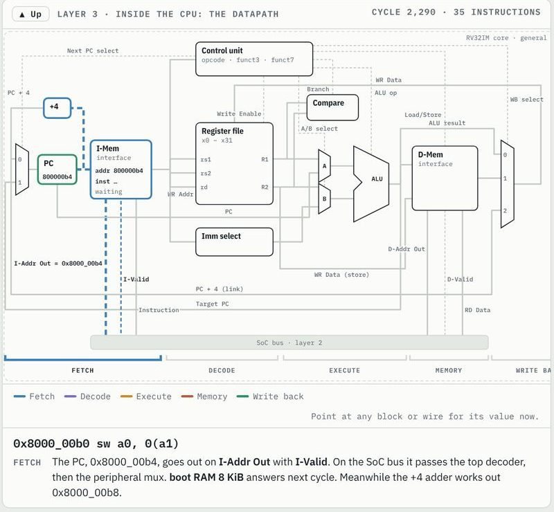
The decoder told us what an instruction wants. Now we have to do it. Almost every RV32I instruction is one of four things: arithmetic (add, compare, shift, logic), a branch or jump (change the PC), a load or store (talk to the bus), or loading a constant. We build a unit for each, then the state machine that runs them in order.
The ALU
The ALU takes two 32-bit values and an operation code, and gives one result. Its operation code is {alt, funct3}, taken straight from the instruction as we saw in part 4:
6// op is {alt, funct3}, i.e. the RISC-V OP/OP-IMM encoding itself:7// 0000 ADD 1000 SUB 0001 SLL 0010 SLT 0011 SLTU8// 0100 XOR 0101 SRL 1101 SRA 0110 OR 0111 ANDOne adder for four operations
An adder is the most expensive part of an ALU, so ours has only one. Subtraction is addition of the two's complement: a - b = a + ~b + 1. The comparisons slt and sltu are subtractions too: you compute a - b and look at the result.
24// a - b for SUB/SLT/SLTU, a + b otherwise25wire sub = alt || f3 == 3'b010 || f3 == 3'b011;26wire [32:0] sum = {1'b0, a} + {1'b0, sub ? ~b : b} + {32'd0, sub};27 28wire ltu = !sum[32];29wire lt = a[31] != b[31] ? a[31] : sum[31];The adder is 33 bits wide so we keep the carry. For unsigned compare, a < b exactly when a - b borrows, i.e. when the carry out is 0 (line 28). For signed compare (line 29): if the signs differ, the negative one is smaller, so the answer is a's sign bit; if they are the same, the subtraction cannot overflow and its sign bit is the answer.
One shifter for both directions
Shifting left and right would need two barrel shifters. Instead, a left shift is done by reversing the bits, shifting right, and reversing again:
31function [31:0] reverse(input [31:0] x);32 integer i;33 for (i = 0; i < 32; i = i + 1)34 reverse[i] = x[31 - i];35endfunction36 37wire left = f3 == 3'b001;38wire [31:0] sh_in = left ? reverse(a) : a;39wire sh_fill = alt && a[31];40wire [32:0] sh_wide = $signed({sh_fill, sh_in}) >>> b[4:0];41wire [31:0] sh_out = sh_wide[31:0];sh_fill is the bit shifted in from the top: the sign bit for sra (arithmetic right shift), zero otherwise. Bit reversal is just wiring, so it costs nothing in the FPGA.
Then a case on funct3 picks the result:
43always @* begin44 case (f3)45 3'b000: y = sum[31:0];46 3'b001: y = reverse(sh_out);47 3'b010: y = {31'b0, lt};48 3'b011: y = {31'b0, ltu};49 3'b100: y = a ^ b;50 3'b101: y = sh_out;51 3'b110: y = a | b;52 default: y = a & b;53 endcase54endBranches
A branch compares two registers and, if the condition holds, jumps. RISC-V has six: beq, bne, blt, bge, bltu, bgeu. Look at their funct3 values and a pattern appears: bits 2:1 pick the comparison and bit 0 inverts it.
11module nt_branch (12 input [ 2:0] funct3,13 input [31:0] a,14 input [31:0] b,15 output reg taken16);17 wire eq = a == b;18 wire lt = $signed(a) < $signed(b);19 wire ltu = a < b;20 21 always @* begin22 case (funct3[2:1])23 2'b00: taken = eq;24 2'b10: taken = lt;25 2'b11: taken = ltu;26 default: taken = 1'b0;27 endcase28 if (funct3[0])29 taken = !taken;30 endbne is "not beq", bge is "not blt". Three comparators and an inverter cover all six.
Computing addresses and the next PC
In the execute stage one more adder, the AGU (address generation unit), computes either a memory address (rs1 + imm for loads, stores and jalr) or a jump target (pc + imm for jal, branches and auipc):
61assign agu = (rs1_based ? id_rs1 : id_pc) + id_imm;62 63// JALR clears bit 0; for JAL and branches it is already 064wire [31:0] target = {agu[31:1], 1'b0};65wire taken = id_jal || id_jalr || (id_branch && branch_taken);66 67assign next_pc = taken ? target : pc_plus4;68assign jump_misaligned = taken && target[1];next_pc is the target if the instruction jumps, pc + 4 otherwise. If a jump target is not a multiple of four, that is an exception: RV32I without compressed instructions cannot run from there.
And what gets written to rd:
70assign result = id_jal || id_jalr ? pc_plus4 :71 id_lui ? id_imm :72 id_auipc ? agu :73 id_csr ? csr_rdata :74 alu_y;jal and jalr save the return address pc + 4 (that is how function calls work: jal ra, f jumps to f and leaves the way back in ra). lui writes its immediate directly; auipc writes pc + imm, which is how position-independent code finds addresses. Everything else is the ALU result.
Loads and stores
The bus is 32 bits wide and word aligned, but C uses bytes and halfwords all the time. The load/store unit bridges the two. For a store it puts the data in every byte lane it could go to, and sets the write strobes for the bytes actually written:
38assign bus_addr = {addr[31:2], 2'b00};39 40reg [3:0] mask;41always @* begin42 case (size)43 2'b00: begin44 bus_wdata = {4{store_data[7:0]}};45 mask = 4'b0001 << ofs;46 end47 2'b01: begin48 bus_wdata = {2{store_data[15:0]}};49 mask = ofs[1] ? 4'b1100 : 4'b0011;50 end51 default: begin52 bus_wdata = store_data;53 mask = 4'b1111;54 end55 endcase56end57 58assign bus_wstrb = is_store ? mask : 4'b0000;A store byte to address 0x4000_0003: the bus address becomes 0x4000_0000, the byte is copied into all four lanes, and the mask 0001 << 3 = 1000 tells the memory to write only the top byte. Every device's merge function from part 3 does the rest.
For a load, the word comes back and the right bytes have to be shifted down and sign- or zero-extended:
60wire [31:0] shifted = bus_rdata >> {ofs, 3'b000};61wire sext = !funct3[2];62 63always @(posedge clk) begin64 if (load_we) begin65 case (size)66 2'b00: load_data <= {{24{sext && shifted[ 7]}}, shifted[ 7:0]};67 2'b01: load_data <= {{16{sext && shifted[15]}}, shifted[15:0]};68 default: load_data <= bus_rdata;69 endcase70 end71endlb and lh copy the sign bit up (sext); lbu and lhu (funct3 bit 2 set) fill with zeros.
The state machine
Now the conductor. The control unit is a small state machine that says, in each cycle, which register to enable and whether to start a bus access. The comment at the top of the file draws it:
6// BOOT -> FETCH -> DECODE -> EXECUTE -> FETCH (all others; a7// multiply/divide8// stays in EXECUTE9// until md_wait falls)10// |11// +-> MEM -> WB -> FETCH (loads, stores)12// +-> TRAP (exception, until reset)Here is the normal (non-debug) version. First the outputs, each one a single comparison with the state:
118wire ex_done = state == S_EXECUTE && !exception &&119 !is_mem && !md_wait;120assign commit = ex_done || state == S_WB;121assign ir_we = state == S_FETCH && bus_done;122assign id_we = state == S_DECODE;123assign ls_req = state == S_EXECUTE && !exception && is_mem;124assign load_we = state == S_MEM && bus_done;125assign wb_load = state == S_WB;126assign if_req = commit || state == S_BOOT;127assign trap = state == S_TRAP;128assign executing = state == S_EXECUTE;129assign halted = 1'b0;commit is the moment an instruction is done: at the end of Execute for most, at the end of Write back for loads and stores. On commit, the PC and rd are written and the next fetch starts in the same cycle (if_req = commit), which is why the fetch stage used next_pc directly.
And the transitions:
135case (state)136 S_BOOT: state <= S_FETCH;137 S_FETCH: if (bus_done) state <= S_DECODE;138 S_DECODE: state <= S_EXECUTE;139 S_EXECUTE: state <= exception ? S_TRAP :140 is_mem ? S_MEM :141 md_wait ? S_EXECUTE : S_FETCH;142 S_MEM: if (bus_done) state <= S_WB;143 S_WB: state <= S_FETCH;144 default: state <= S_TRAP;145endcaseFetch waits as long as the bus does (bus_done). Execute goes to Mem for loads and stores, stays in Execute while a divide is still running (md_wait), and goes to Trap on an exception. Trap is a dead end until reset: NandTier has no operating system to handle errors, so stopping visibly is the most honest thing to do.
add and a lw, cycle by cycle. The bus request goes out in FETCH and MEM; the commit pulse ends each instruction.Counting cycles: an ALU instruction from memory that answers in one cycle takes Fetch (2) + Decode (1) + Execute (1) = 4 cycles. A load or store adds Mem (2) and Write back (1): 7 cycles. At 25 MHz that is about 6 million instructions a second, plenty for our games.
Testing it against a reference
A CPU has to be right for every instruction and every operand. The project checks the ALU against plain Verilog operators on corner cases and thousands of random values:
25function [31:0] expected(input [3:0] op, input [31:0] a, input [31:0] b);26 case (op)27 4'b0000: expected = a + b;28 4'b1000: expected = a - b;29 4'b0001: expected = a << b[4:0];30 4'b0010: expected = $signed(a) < $signed(b) ? 1 : 0;31 4'b0011: expected = a < b ? 1 : 0;32 4'b0100: expected = a ^ b;33 4'b0101: expected = a >> b[4:0];34 4'b1101: expected = $signed(a) >>> b[4:0];35 4'b0110: expected = a | b;36 4'b0111: expected = a & b;37 default: expected = 32'hxxxx_xxxx;38 endcase39endfunctionAnd the whole core runs random programs whose results are compared with an instruction-set simulator written in Python:
$ make -C test unit$ make -C test random SEEDS="1 2 3"Conclusion
That is a complete RV32I processor: fetch, decode, an ALU that shares one adder, branches in a few gates, a load/store unit for bytes on a word bus, and a seven-state machine to drive it. It is small enough to read in an afternoon, and it runs code straight from GCC.
What code, though? When the board powers on, the boot RAM must already hold a program. In the next article we write that first program and look at what GCC and the linker need to put it there.