DVI on HDMI from Scratch: Timing and TMDS
Count pixels and lines, turn every 8-bit colour into a balanced 10-bit symbol, and send three of them a pixel over four wire pairs at 250 Mbit/s.
In this article
What are we trying to do?
We want a picture on a monitor. The Tang Nano 9K's HDMI connector is wired straight to eight FPGA pins, four differential pairs, with no video chip in between. So the FPGA itself has to produce the signal a monitor expects, bit by bit.
The format we will produce is the oldest and simplest one every HDMI monitor accepts: 640 × 480 at 60 Hz, sent as DVI (HDMI's video part, without audio). Three steps:
- Timing: count pixels and lines, and say when a pixel is visible and when the sync pulses are.
- Encoding: turn each 8-bit colour into a 10-bit TMDS symbol.
- Serialising: send the 10 bits of each symbol in one pixel time, on three data pairs plus a clock pair.
The timing
A monitor still thinks like a CRT: it draws lines left to right, top to bottom, and needs gaps between them. Each line and each frame has a visible part, a front porch, a sync pulse and a back porch:
9// visible front porch sync back porch total10// horiz. 640 16 96 48 80011// vert. 480 10 2 33 525800 × 525 = 420,000 pixel clocks per frame. At 60 frames a second that is 25.2 MHz; the standard says 25.175 MHz. Our system clock is 24.975 MHz, a little slow, which gives 59.5 Hz; every monitor we have tried accepts it. And because the pixel clock is the system clock, the CPU and the video run in lockstep: one frame is exactly 420,000 CPU cycles. Remember that number for part 11.
The counters:
31wire x_last = x == H_TOTAL - 1;32wire y_last = y == V_TOTAL - 1;33wire [9:0] nx = x_last ? 10'd0 : x + 10'd1;34wire [9:0] ny = !x_last ? y : y_last ? 10'd0 : y + 10'd1;x counts 0 to 799 and wraps; y steps once per line. Everything else is a comparison on the next position (nx, ny), registered so all outputs belong to the same pixel:
44x <= nx;45y <= ny;46visible <= nx < H_VISIBLE && ny < V_VISIBLE;47hsync <= (nx >= H_VISIBLE + H_FRONT && nx < H_VISIBLE + H_FRONT + H_SYNC) ?48 SYNC_ACTIVE : !SYNC_ACTIVE;49vsync <= (ny >= V_VISIBLE + V_FRONT && ny < V_VISIBLE + V_FRONT + V_SYNC) ?50 SYNC_ACTIVE : !SYNC_ACTIVE;visible is true in the 640 × 480 area. The sync pulses are low (SYNC_ACTIVE = 0) during the sync part of the blanking, as the VESA standard for this mode says.
TMDS: why not just send the bits?
The three colour channels each carry 8 bits per pixel. At 25 MHz that is 200 Mbit/s per wire pair, and fast serial lines have two enemies: long runs of the same bit (the receiver loses track of where bits are) and DC imbalance (more ones than zeros over time, which the AC-coupling capacitors on the board would slowly block). TMDS, Transition-Minimised Differential Signalling, fixes both by sending 10 bits for every 8.
Stage 1: fewer transitions
Each bit is XORed (or XNORed) with the previous output bit, whichever gives fewer changes. The rule for which:
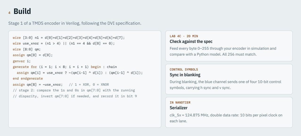
32// stage 1: transition minimisation33wire use_xnor = ones(data) > 4'd4 || (ones(data) == 4'd4 && !data[0]);34 35reg [8:0] q_m;36integer i;37always @* begin38 q_m[0] = data[0];39 for (i = 1; i < 8; i = i + 1)40 q_m[i] = use_xnor ? !(q_m[i-1] ^ data[i]) : (q_m[i-1] ^ data[i]);41 q_m[8] = !use_xnor;42endones(data) counts the 1 bits. With more than four ones, XNOR makes fewer transitions. Bit 8 of q_m records which was used, so the receiver can undo it.
Stage 2: balance
Now the running disparity: how many more ones than zeros we have sent so far on this line. Each symbol may be sent as is or with its 8 data bits inverted, whichever moves the running total towards zero:
44// stage 2: DC balance. disparity = (#ones - #zeros) of q_m[7:0]45wire [5:0] twice_ones = {1'b0, ones(q_m[7:0]), 1'b0}; // 0..1646wire signed [5:0] disp_wide = $signed(twice_ones) - 6'sd8; // -8..847wire signed [4:0] disparity = disp_wide[4:0];48reg signed [4:0] bias; // running disparity, in units of one bit49 50wire bias_zero = bias == 5'sd0;51wire balanced = disparity == 5'sd0;52wire same_sign = bias[4] == disparity[4];disparity is the imbalance of this symbol, bias the running total, in units of one bit.
66end else if (bias_zero || balanced) begin67 symbol <= {!q_m[8], q_m[8], q_m[8] ? q_m[7:0] : ~q_m[7:0]};68 bias <= q_m[8] ? bias + disparity : bias - disparity;69end else if (same_sign) begin70 // bias and data lean the same way: send the data inverted71 symbol <= {1'b1, q_m[8], ~q_m[7:0]};72 bias <= bias - disparity + (q_m[8] ? 5'sd2 : 5'sd0);73end else begin74 symbol <= {1'b0, q_m[8], q_m[7:0]};75 bias <= bias + disparity - (q_m[8] ? 5'sd0 : 5'sd2);76endThree cases from the DVI specification: if either the total or this symbol is balanced, choose by bit 8; if they lean the same way, invert (bit 9 = 1) to pull back; otherwise send as is. Bit 9 tells the receiver whether to invert back.
Control symbols
During blanking there is no colour to send. Instead each channel sends one of four special 10-bit control symbols, which carry hsync and vsync on the blue channel:
58end else if (!de) begin59 bias <= 5'sd0;60 case (ctrl)61 2'b00: symbol <= 10'b1101010100;62 2'b01: symbol <= 10'b0010101011;63 2'b10: symbol <= 10'b0101010100;64 2'b11: symbol <= 10'b1010101011;65 endcaseThese four have many transitions and look like no data symbol, which is how the receiver finds the boundary between symbols in the first place.
Ten bits in one pixel time
Each pixel now has three 10-bit symbols, and all ten bits must go out within one 40 ns pixel time: 250 Mbit/s per lane. No FPGA logic runs that fast, but the GW1NR-9 has dedicated serialisers in its I/O blocks. OSER10 takes 10 bits at the pixel clock and shifts them out using a clock five times faster, on both edges:
135wire [9:0] lane [0:3];136assign lane[0] = sym0;137assign lane[1] = sym1;138assign lane[2] = sym2;139assign lane[3] = 10'b0000011111;140 141wire [3:0] serial;142 143genvar n;144generate145 for (n = 0; n < 4; n = n + 1) begin : tmds_lane146 OSER10 u_ser (147 .Q(serial[n]),148 .D0(lane[n][0]), .D1(lane[n][1]), .D2(lane[n][2]), .D3(lane[n][3]), .D4(lane[n][4]),149 .D5(lane[n][5]), .D6(lane[n][6]), .D7(lane[n][7]), .D8(lane[n][8]), .D9(lane[n][9]),150 .PCLK(clk), .FCLK(clk_5x), .RESET(!resetn)151 );152 endFour lanes: the three colour channels and the clock. The clock lane does not use a serialiser trick at all; it sends the constant pattern 0000011111, which is a square wave at the pixel clock: five bits high, five low.
clk_5x is the 124.875 MHz clock from the PLL in part 1. That is why the SoC runs at 24.975 MHz: it is clk_5x / 5, the pixel clock, in phase with the serialisers.
Each serial stream then goes to a differential output buffer:
161end else begin : elvds162 ELVDS_OBUF u_out_d0 (.I(serial[0]), .O(tmds_d_p[0]), .OB(tmds_d_n[0]));163 ELVDS_OBUF u_out_d1 (.I(serial[1]), .O(tmds_d_p[1]), .OB(tmds_d_n[1]));164 ELVDS_OBUF u_out_d2 (.I(serial[2]), .O(tmds_d_p[2]), .OB(tmds_d_n[2]));165 ELVDS_OBUF u_out_clk (.I(serial[3]), .O(tmds_clk_p), .OB(tmds_clk_n));166endThe 9K's I/O banks for those pins have no true LVDS drivers, so ELVDS_OBUF emulates one with two ordinary outputs driven in opposite directions. It works because the board has the termination and capacitors HDMI needs.
Words on the screen
The very first thing NandTier shows is text. A text terminal (80 × 25 characters in a small bitmap font) sits on top of the picture, and every byte written to the UART is also drawn there; we saw the wire for it in part 2:
275// every byte written to the UART data register also goes to the screen276wire term_valid = per_valid[3] && per_ready[3] && !cpu_addr[2] && cpu_wstrb[0];So with nothing more than the UART code from part 2, the launcher's menu appears on the monitor as well as in the PC terminal. The terminal handles newline, carriage return, backspace, tab and form feed, and scrolls when it reaches the bottom.
Conclusion
A picture on an HDMI monitor takes two counters, an encoder that balances ones and zeros, and the FPGA's serialisers doing 250 million bits a second per lane. No video chip, just logic and four pairs of wires.
Text is a start, but games need pictures that move. In the next article we build a small graphics chip, the PPU, that draws tiles and sprites into this video stream.